Parts of a Wind Turbine
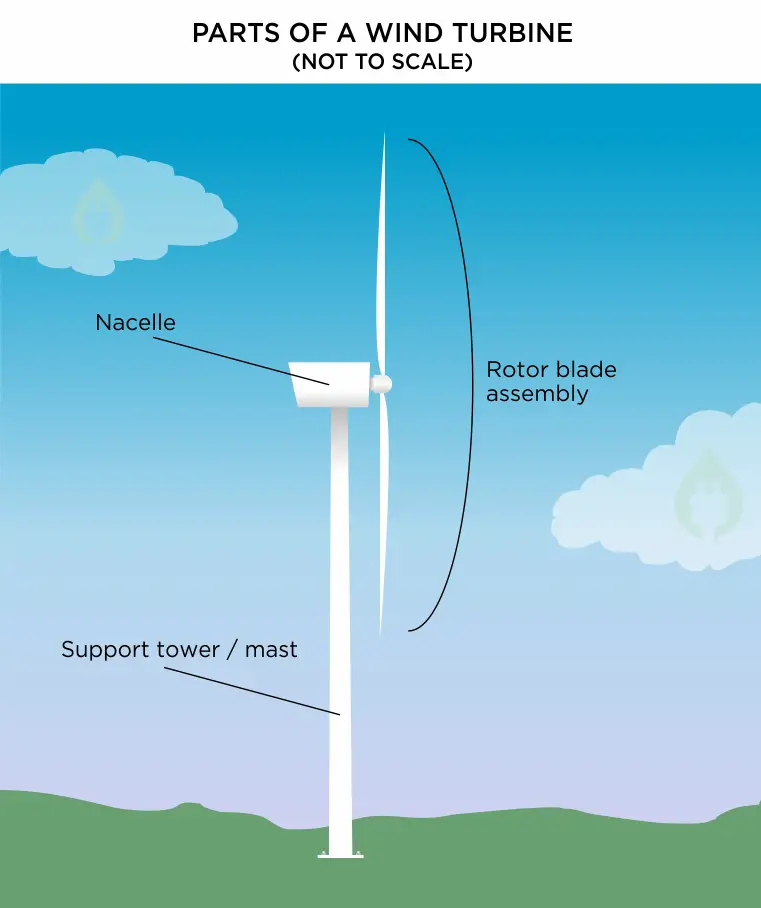
1. Support tower / mast
2. Nacelle
3. Rotor Blades
1. Support Tower / Mast
The main support tower is made of steel, finished in a number of layers of protective paint to shield it against the elements. The tower must be tall enough to ensure the rotor blade does not interfere with normal day-to-day operations at ground level (for instance with turbine shadow flicker).
A smaller, on-shore 2MW wind turbine has a support tower 256 feet tall, with rotor blades 143 feet long. This means that the lowest point of the sweep of the rotor blades is 113 feet from the ground – a safe distance up.
To ensure the tower is securely attached to the ground, first a 15 to 20 foot deep concrete foundation pad is poured, requiring approximately 30,000 tons of cement.1 The anchor bolts for the tower are embedded deep into the concrete pad itself.2
The tower is then securely bolted onto this concrete foundation pad. The tower itself must also be strong enough to hold up the nacelle and the rotor blades in all weathers. The weight of the steel support pillar alone for a 2MW wind turbine is 220 tons.3
2. Nacelle
The nacelle is the ‘head’ of the wind turbine, and it is mounted on top of the support tower. The rotor blade assembly is attached to the front of the nacelle.
The nacelle of a standard 2MW onshore wind turbine assembly weighs approximately 72 tons.
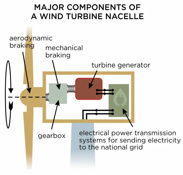
Housed inside the nacelle are five major components (see diagram):
a. Gearbox assembly
b. Aerodynamic braking system
c. Mechanical braking system
d. Turbine generator
e. Electrical power transmission systems
a. Gearbox Assembly
The gearbox assembly receives the rotating input shaft from the centre of the rotor blade assembly, and using a system of gears, speeds up the rotation to a high speed suitable for running the turbine generator at its optimum generation speed. The high speed output shaft from the gearbox then directly drives the rotation of the generator.
b. Aerodynamic Braking
All modern wind turbines use two different kinds of braking systems – aerodynamic braking and mechanical (friction) braking.
Aerodynamic braking, or “rotor feathering” as it is sometimes called, is achieved by twisting the rotor blades so they present a thinner cross section to the oncoming wind; This means they ‘catch’ less of the wind, and so rotate slower.
c. Mechanical Braking
The mechanical braking system is incorporated into the gearbox assembly. Mechanical braking is just another term for friction braking – identical to what you would find in a motor vehicle’s brakes. A rotating disc is mounted onto the input shaft of the gearbox, and using a hydraulic actuator, brake pads are clamped onto the disc, thus gradually slowing the blade assembly to a complete stop.
Under the vast majority of wind speeds, the mechanical braking systems do not need to be used under normal operation – the rotation speed of the blades is controlled using aerodynamic braking alone. Mechanical brakes are only used if the turbine needs to be stopped completely; for example, to allow workers to carry out maintenance or to stop the turbine generating if there is too much power on the electrical grid.4
d. Turbine Generator
The turbine generator is the component that turns the rotational energy in the high-speed output shaft from the gearbox into an electrical current. The electrical principle of electromagnetic induction shows that while a magnet is moving past a coil of wire, an electric current is created (or “induced”) in the wire.
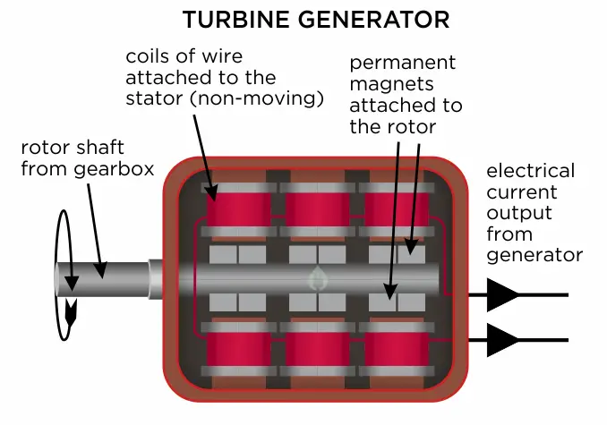
Inside the generator, there are two main components – the rotor and the stator. The rotor is all the bits that rotate, and the stator is all the bits that don’t. Some systems use rotating magnets against static coils of wire, and some systems use rotating coils of wire against static magnets, but the end result is the same – an electric current is generated at the output of the coils.
The cross-section illustration above shows a generator that has the magnets attached to the rotor, and the coils attached to the stator. As the rotor shaft turns round, the magnets spin past the coils that are mounted all around the rotor, and an electric current is induced in the coils. The coils are all wired together to increase the power, and the wires carrying the current are routed through the shell of the generator to be sent to the next system.
e. Electrical Power Transmission Systems
The electrical current from the generator is not yet ready for sending to the national electricity grid, and so it is first fed into a series of electrical circuits that transform the voltage to the appropriate level such that it can be connected with optimum efficiency to the grid. This electrical power is then fed through cables back down inside the support tower where it is taken to connect to the grid. From there, that electricity is supplied for use by homes and businesses.
3. Rotor Blades
The rotor blades are the three (usually three) long thin blades that attach to the hub of the nacelle. These blades are designed to capture the kinetic energy in the wind as it passes, and convert it into rotational energy.
The largest wind turbines being manufactured in the world (as of 2021) are 15MW turbines. These turbines have rotor blades just over 115m long.5 When rotating at normal operational speeds, the blade tips of a 15MW wind turbine sweep through the air at approximately 230 mph!6
To withstand the very high stresses they experience, wind turbine blades are made from modern composite materials like carbon fibre or glass fibre to give the most amount of strength and rigidity for the least amount of weight. Under normal operating conditions, a wind turbine blade is expected to give 20 -25 years of service before it needs to be recycled and replaced.7
References
1. https://www.windpowerengineering.com/
2. https://www.williamsform.com/
3. https://www.wind-watch.org/
4. http://xn--drmstrre-64ad.dk/
5. https://www.compositesworld.com/
7. https://www.renewablesfirst.co.uk/
Featured Image Credit ©zvonce1959/123RF.COM


